
What is a macro?
Essentially, a macro is a single device that captures the functionality of an entire network of World Machine devices. Macros consist of an inside macroworld that is connected via ports to the outside world.
Macros are user-created, and can be saved and traded between users, essentially offering an easy way to encapsulate and exchange useful effects. The power of macros come especially into play when they are parameterized, as they then can contain options, controls, and parameters just like any other device you can place into the network. Extremely powerful macros rivaling custom-programmed device plugins can be created.
Using Macros
Installing a Macro
The macro system has been designed to be easy for you to organize into whatever hierarchies you prefer. To do so, simply open up the World Machine Macro folder (/macros) from the folder you installed WM into.
You can now create subfolders and drag and drop macros to and from them using Windows Explorer! Your changes will be reflected in World Machine upon startup
Inserting a Macro into your world
Adding a macro to your world is simple: from the menu bar, select Macros>Load Device from Library. You will be presented with a list of the macros installed on your machine.
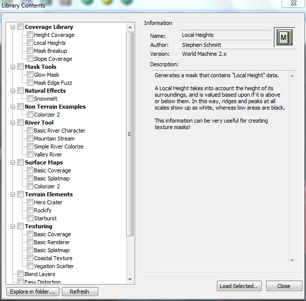
Clicking on a macro reveals details about it on the right, such as the author, what version of World Machine the macro was created for, and a description of the macro. After you’ve selected the macro you want, simply click OK to choose that macro. It is now the active drop-device just as if you had clicked on a device in the toolbar. Click anywhere in the workview to place the macro device there.
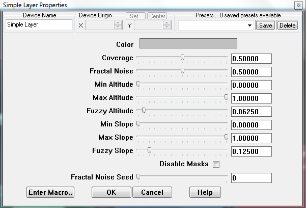
In your deviceworld, macros behave exactly like any other device. They have required and optional input ports, parameters that can be adjusted, and so on.
Authoring Macros
Creating the macro
There are two methods you can use to create a macro.
1) You can create a blank macro. Do this by executing the command Heightfield Operators->Utilities- >Blank Macro, and click in the work view. The macro will default to having no ports and no internal devices – it is a blank slate ready for your customization.
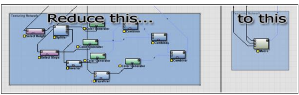
2) You can convert an existing section of your network into a macro. This option is particularly useful if you’ve created a specific effect that you want to save and possibly use again in the future.
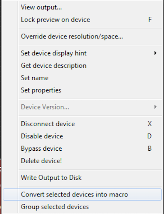
To do this, select one or more devices and then right-click on one of them and choose “Create Macro” from the pop-up menu. The selected devices will be placed inside of a new macro, and ports will be created on the macro device so that all links into and out of the internal devices will be re-routed with no change in overall network functionality.
Inside the Macro World
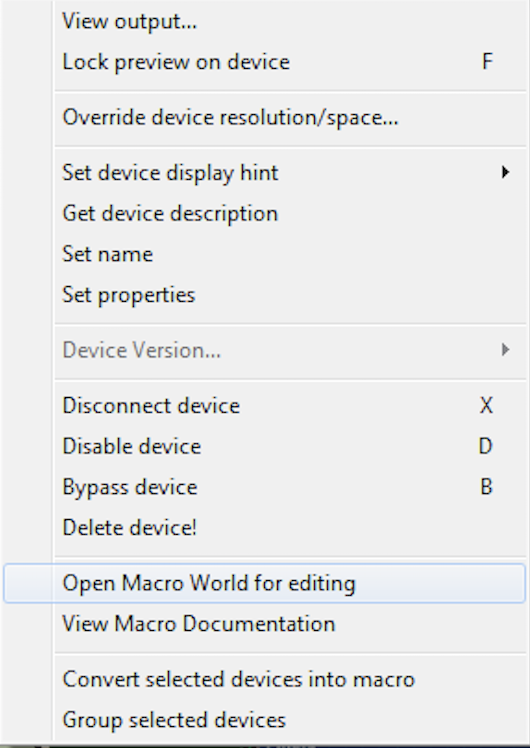
Once your macro is created by any method, you can enter the Macro World to edit it. There are two ways to do this:
● you can edit the macro by right clicking on it and selecting “Open Macro World for Editing”.
● You can double click on the macro then choose “Enter Macro”.
Doing so will change the workview dramatically. The outside device network is nowhere to be seen! Instead, you see several new unfamiliar devices, plus any devices you might have converted to a macro earlier in 8.2.1.
Don’t be worried; the outside world is not actually gone. Instead, WM is now showing you the inside of the macro device. A line of tabs will have appeared across the top of the workview, showing you which world you are editing.

You can change back and forth from the macro to the outside by click on a tab; right-clicking on a tab will close the view of that macro.
Macros can be more than one layer deep – your macros may also use macros that consist of still more macros, and so on. You can “tunnel” in as far as you want.
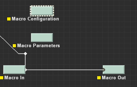
There are four permanent devices inside of all macros. They cannot be deleted — they are integrated parts of the macro that are exposed for your use. These devices are:
• Macro In : Represents the place where outside information flows into the macro world
• Macro Out : The place where the results of the macroworld’s calculations return to the parent world
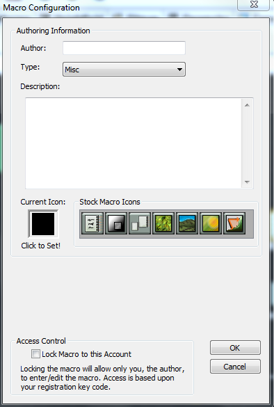
• Macro Config : A place to provide a description of the macro, as well as information such as the author’s name
• Macro Parameters : The most complicated of the four macro devices, The Parameter device allows the outside user to interact and change device network settings inside the macro without having to open the macro up to modify it. This is an extremely powerful ability, so much so that several entire chapters will be devoted to describing how best to use this feature.
These four devices are the portals through which information can flow between the outside world and the inner world of the macro. You can configure them in the same way as any other device – by double- clicking them.
Ports
The Macro In and Macro Out devices control the ports on the macro. They are identical except that for the fact that one is devoted to input; the other to output.
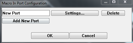
To add another port to the macro, simply click “Add New Port”. You can then give it any name you want to describe the purpose of it.
Similarly, to delete a port from the macro, click the delete button next to that entry to flag it for deletion. The port will be deleted when you click “OK” on the dialog.
The “Settings” button brings up a dialog that allows you to configure that port.
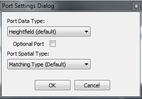
The primary decision to make is what kind of data the port will accept. The default is heightfield data, but you can set the data type to bitmap, text, or to accept any type of data. You can flag a port as “optional” as well. A normal port is one that is required for operation of the macro. If a normal input is not connected, the macro will not function. An optional input signifies a port that is not absolutely required for proper operation. A typical use of this might be, for example, for an input to allow the user to override a default terrain used inside of the macro, or to specify an optional mask whereby the macro is only applied in certain areas. For outputs, the optional flag is usually used to denote an auxiliary output; perhaps an erosion mask for texturing or something else that is a useful but unnecessary result of the macro.
Macro Configuration
Parameters
Parameters are the most powerful aspect of macros. Section 8.3 will delve into them in great detail; here we only concern ourselves with the actual options shown in the dialogs.
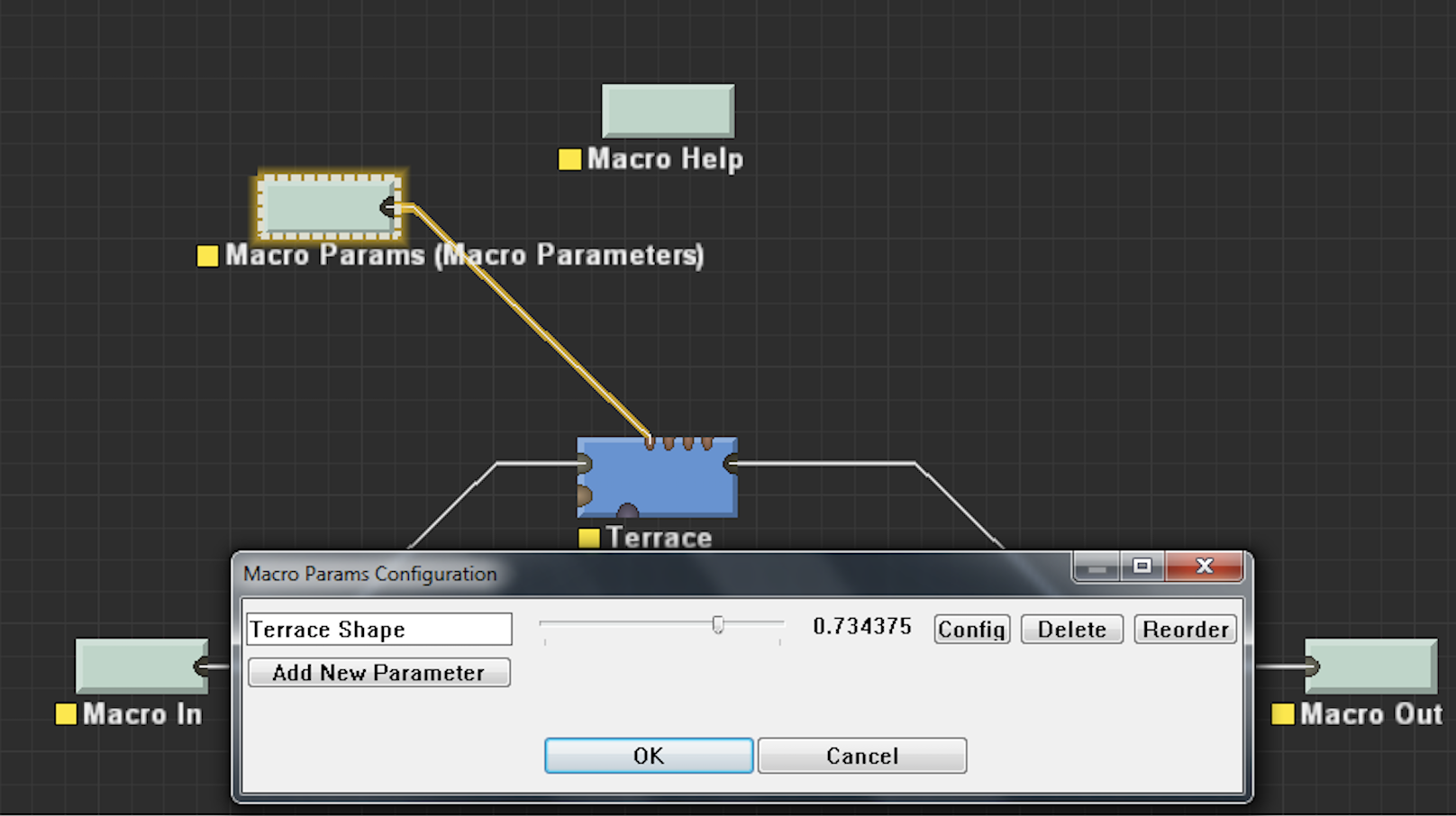
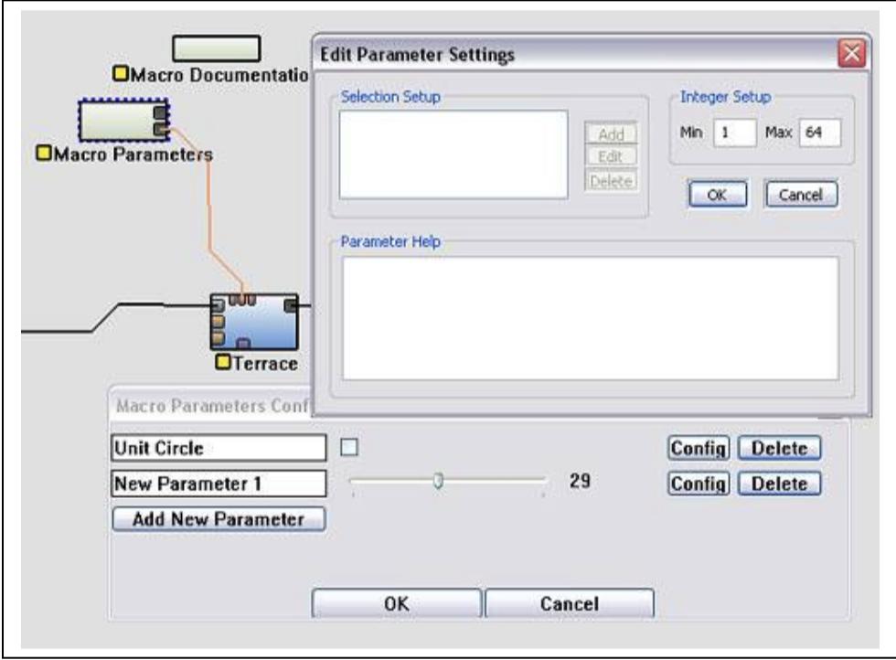
The parameter device looks like this:
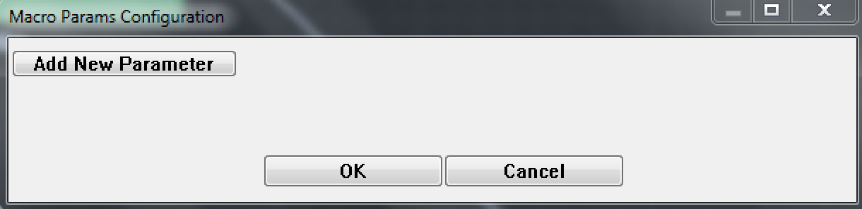
As can be seen above, from the main Macro Parameter screen you can do the following things:
1) Add new parameters. Click on the “Add Parameter” button to add a new parameter to the macro. You will then be presented with a choice of the type of parameter you wish to create.
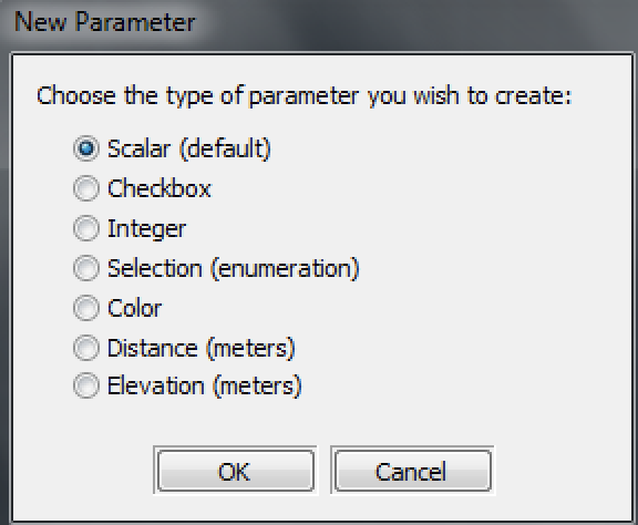
The default parameter type is a scalar; this can be directly used to adjust any device parameter in World Machine. However, several other types are possible and will be useful depending on the purpose of the macro. For a full discussion of parameter types, see section 8.3.
2) Change the current value of a parameter. Adjusting the slider or entering a new value is exactly equivalent to doing the same thing to the outside of the macro device.
3) Rename a parameter. This is pretty self-explanatory!
4) Flag a parameter for deletion. Like the Port device, parameters are only deleted once you click OK in the parameter dialog.
5) Configure any advanced options and help tool tip for each parameter.
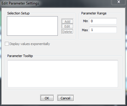
For every parameter, you can assign help text that will appear if the user hovers the mouse over the parameter. The tool tip text should be one or two sentences that give the user a better idea about what adjusting the parameter will do.
The other sections in this dialog are only valid for particular types of parameters:
Selections
● You can add, edit or delete selection entries. Every entry you add here will show up as an option to select from in a list box in the macro.
Integers
● You can specify the minimum and maximum values of an integer to control the range of the parameter.
See section 8.3.3 for more details about using these types of parameters.
Macro Parameter System
Understanding the way that macro parameters, scalar networks, and device parameters interact is critical to being able to create useful and effective macros.
Device Parameters Inputs:
In Chapter 1 we mentioned Parameter Input ports along the top of the devices. They are essential for controlling parameters inside of macros. These appear when a device is selected; you can see the difference below:
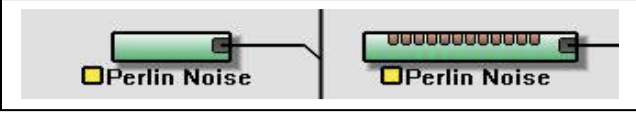
Simple Parameters
In this case the parameter that you manipulate in the macro is a direct link to the internal device’s parameter. It’s as if the user could reach into the macro and adjust that device directly. This is the simplest and easiest to understand use of macro parameters.
To create a simple parameter, create a scalar parameter as in 4.2.5, naming it as you desire.
After you click OK, the Macro Parameter device will have a new output port. Simply wire that port into the parameter input port of the parameter you want to change.
Note that wires that carry scalar or parameter data are orange, not black. Each type of data that is carried in the network has a different wiring color code. Any future data types added to World Machine would similarly have different link colors.
Scalar Device Networks
Sometimes you want to do more than is possible with simple parameters. For example, you may want to adjust two related parameters at the same time when the user adjusts a control. The solution to this is scalar device networks.

The scalar devices are accessible from the Parameter Operators menu bar. They are also the devices in the parts toolbar with a light blue background shown above.
From left to right, they are the Automation Scalar, Scalar Generator, Scalar Clamp, Scalar Inverter, Scalar Arithmetic, Scalar Combiner, Bank Selector, Integer Generator, Transform, Distortion Generator and Integer Equals.
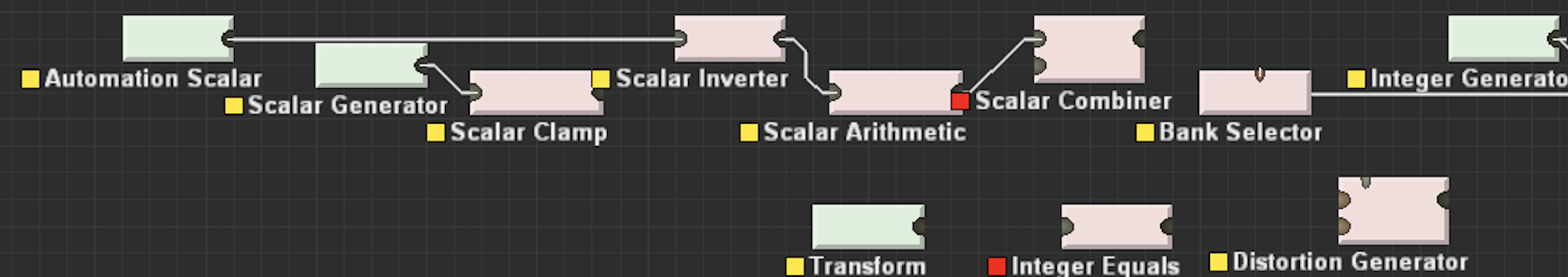
Above is a typical scalar device network. What is it doing?
1) The Scalar Generator creates a number, such as .35.
2) The Scalar Clamp rescales the range of values. Thus, a 0.0 input into the clamp might become a .25, and a 1.0 input might become a .75. Our value of .35 would be rescaled according to those new ranges – so it would become 0.425.
3) The Scalar Splitter has multiple output ports so that you can use the value for several parameters
4) The scalar value is wired into the Simple Transform device, controlling both the Canyonize and Glaciate parameters.
So in effect, adjusting one control now adjusts two parameters instead of one – and the adjustments are constrained to be in a smaller range. With the addition of more devices to the scalar network, we could control more parameters, or have them change differently in regards to each other.
As you can already tell, Scalar networks are strongly mathematical in nature, and can be quite complicated. Most of the challenge lies in figuring out how you want the different driven parameters to change as the Scalar Generator output changes.
Lastly, notice that you can replace the Scalar Generator in the network with the output from a Macro Parameter device. They are interchangeable.
Non-scalar Parameters
Scalars are not the only type of parameter that you can drive from a macro:
Booleans
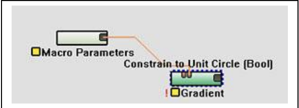
A Boolean (checkbox) parameter should be used when you want to drive a Boolean device parameter. Above, a Boolean is being used to drive the “Constrain to Unit Circle” parameter on the Gradient device, which as can be noted by the (Bool) on the right of the parameter name, takes a Boolean
parameter.
Integers
Integer Macro Parameters are useful for driving the integer parameter input ports of some devices. Above, an Integer parameter is being used to drive the “Number of Terraces” parameter on a Terrace device.
Note that as shown above, in order to use an Integer parameter, you must push the “Config” button in the Macro Parameters dialog for that parameter, and set the range of values that the integer can take on.
Selections
A Selection parameter is, at its core, essentially an integer. However, each value (0,1,2,etc) is labeled. World Machine then presents the user with a list of the labels and allows the user to choose. When used in conjunction with a Bank Selector (see below), Selection parameters become extremely useful.
Bank Selectors
The Bank Selector is a powerful utility device designed for parameters. Its purpose is to allow you to drive many scalar values with the input of a single parameter. Doing this allows you to setup “Styles” inside of your macro, so that with a selection from a simple list box, the user can change many (hidden) parameters at once.
The Bank Selector consists of “tabs” and “variables”. Each variable has an output port on the Bank Selector, and will output a scalar value reflecting its current value. A tab contains a set of values for all of the variables. Thus, by choosing a different tab, you can radically change a whole host of parameters that the user need not be exposed to.
The dialog for it is shown below:
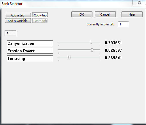
There are 6 actions that can be performed in this dialog:
• Add a variable: Adds a new variable to the Bank Selector. Each variable can be named, and drives a single scalar output value.
• Add a tab: This option creates a new bank of values for all variables
• Copy tab: Copies the variable configuration from the current tab
• Paste tab: Pastes the stored variable configuration to the current tab
• Name a variable: Type a name into the blank area in the variable configuration
• Adjust a variable’s value: Adjust the slider to change what the variable’s value should be in the current tab
• Change tabs: Adjust the tab to be modified by clicking the numbered buttons above the sliders.
The number of buttons will depend upon how many tabs you have created.
The parameter input to a Bank Selector chooses the current tab, and can be either an integer or a selection – the latter is preferred for user friendliness reasons.
Using Heightfield Utility Devices with Macros
Utility devices are those that don’t directly affect the contents of a map; instead, they typically affect the flow of heightfields in the network.
The following utility devices are helpful inside of macros to help direct the flow of data:
Pull-up device
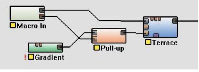
The function of the Pull-up device is to provide a default heightfield if one is not specified. To do this, hook up your reference (default) heightfield to the Reference Input, as shown above. Then the optional heightfield is plugged into the Override Input.
If the Override Input is wired, it will always pass that heightfield along. Otherwise, it will pass the Reference Input along.
Switch device
The Switch device allows you to control which heightfield is passed along to the output with a parameter.
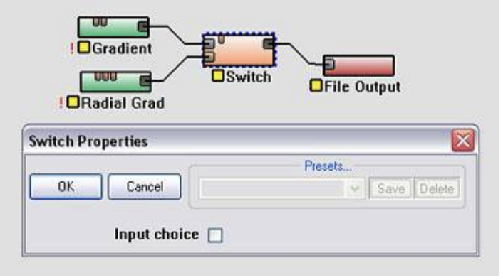
Depending on the value of the “Input choice” checkbox parameter, in the example above either the Gradient or the Radial Gradient will be passed along to the File Output device.
Multi-Splitter & Multi-Chooser
The Multi Splitter and Multi Chooser are designed to allow you to send the terrain data through only one of many paths through the macro at a time. You can set the maximum number of inputs or outputs, as well as control the chosen input or output through a parameter.
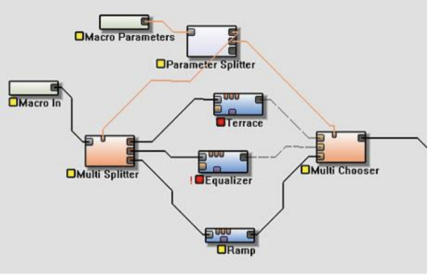
This ability is extremely useful for macros that might have several different effects paths, and where you want to allow the user to choose only one in particular, as in the above illustration. Notice that the paths not currently selected are not built (they have red status icons). This saves the build time and memory for those paths!
Guidelines for Professional Quality Macros
Once you understand the concepts, macros are relatively easy to create. However, to create a professional-quality macro is a different story. There are many design elements, some subtle and others obvious, that go into designing a quality macro. The following guidelines are a good starting point.
Limited Focus
The first guideline is extremely simple – and the most important. The most successful macros are those that are focused and targeted on achieving a certain effect. Try not to do too much in your macro – not only will it become overly complicated, but it loses the reusability that makes macros special. When in doubt, create several macros that can be strung together rather than one monolithic macro that attempts to do many tasks.
Use the right number of parameters
This is perhaps the most often ignored guideline for macros, and the results can be disastrous. There are two sides to err on here:
Too few a number of parameters is the less common problem. It happens when very important or essential user controls have been left out of the interface. The desire for a professional macro is to have something that will be useful to many people and is focused on the task at hand; this means that having a macro where you constantly need to open it up and change things in the macro world is very counterproductive.
On the other hand, a far more common mistake is to expose too many parameters to the user. The first impulse of most macro creators is to include as many parameters as possible, under the assumption that more control is always better. The problem is that presenting a smorgasbord of options to the user is extremely confusing – especially when they have non-descriptive names or only change the output very subtly! Every parameter you add dilutes the attention that a user can give to any particular parameter. It’s all too easy to drown the extremely important parameters under an ocean of irrelevant options.
The best macros will strike a balance between tune-ability and usability. For each parameter, ask yourself if this control is an important addition to the overall operation of the macro. If you cannot answer yes, then don’t provide that parameter! The latest research shows that humans can keep
between 4 and 7 ‘chunks’ of information in their mind at the same time. Keeping this in mind, it would seem to be best to limit the number of parameters to the lower side of that range if possible; and if not, then to group together parameters that do similar things spatially in the dialog, a technique called ‘chunking’.
Another method to reduce the number of parameters is to use scalar device networks or bank selectors to adjust multiple parameters at a time by just controlling a single parameter in the macro itself. See section 4.3.4 for more details on them.
Use the right parameter for the job
In version 0.99 of World Machine, scalars were the only parameters a macro could have. This resulted in people driving integers and even booleans with a scalar parameter. This is both inefficient and very confusing for the user who expects to be able to smoothly change a setting when they adjust a scalar, and instead sees the output suddenly jump from setting to setting!
The rule is simple: if a device uses an integer parameter, drive it with an integer, not a scalar. Likewise for booleans.
Allow only valid parameter ranges
This may be the second most common sin involving macros. A scalar has a valid range of 0.0 through 1.0. If a certain effect is only really useful in the range of 0.2 to 0.5, then why let the user go outside of that range? It’s far more likely to confuse than empower. Use a scalar clamp device to rescale the 0 to 1 range of a macro to the useful range of the effect you’re trying to create.
If you have parameters that are valid only at certain times in certain ranges, a far better option is to use the Bank Selector device to setup banks of settings that change according to a list box parameter in your macro. This allows you to change the parameters that need changing without exposing the user to all of them and potentially leading to confusion.
Use bank selectors! I’m not kidding!
This capability of World Machine has been mentioned several times already in these guidelines simply because they are such a simplifying influence on the user experience for otherwise complex macros. List boxes are an easy and labeled way for the user to interact with the macro. Go here to see details on how to use these devices.
Short-circuit untaken options when possible
If you have several different paths through the inside of the macro world, evaluating all of the devices can be expensive. This is particularly true if, for example, you have a parameter that allows the user to choose between two different erosion devices. A naive implementation of this would calculate both of the devices and then choose between them only at the end.
Instead, you can deactivate those paths that will not be taken! This saves the processing time and memory of those paths that no longer will be built. This is particularly important with macros that are going to be used at high resolutions, as the memory used by a set of devices might spell the difference between what can be created on a machine with a certain amount of RAM and what cannot.
See chapter 4.4.3 for more details on using a Multi-Splitter & Multi-Combiner combination to accomplish this.