
The Layout Generator is a graphical design tool that allows you to bridge the gap between fully procedural and fully artist-created terrains. With a Layout Generator, you have a suite of vector drawing tools that let you craft terrain areas, insert roads and rivers, draw regions of influence as effect masks, and much more.
Layout Generator Basics
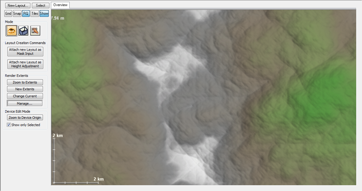
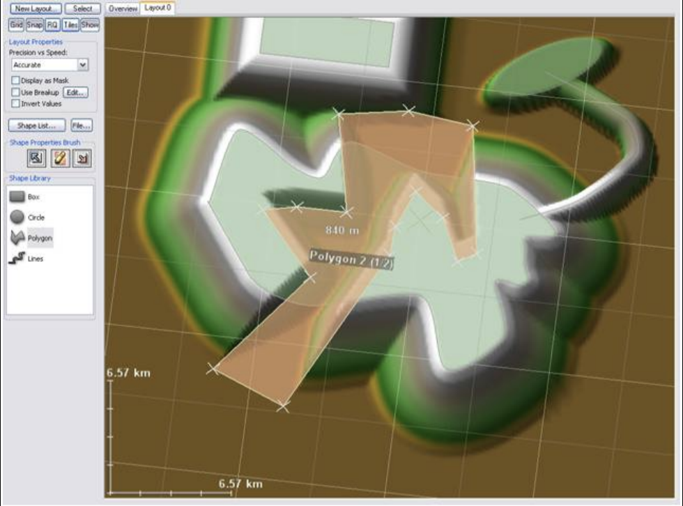
To create a Layout Generator, go to the Layout View:
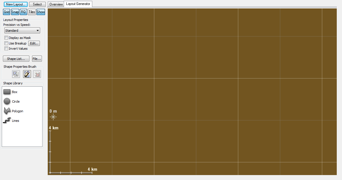
Click the New Layout button in the upper-left corner of the above photo. As you create layout generators, they will appear as tabs across the top of the view.
When a layout is selected in the view, the screen will change to the Layout Editing mode, as you can see below:
A Layout Generator acts as a container for shapes. You can have many different layout generators. each one you create will show up as an associated device in the Device Workview. The output of the layout generator can then be used just like any other component in the workflow.
Also, note that you can change the currently viewed output while editing a layout generator and its shapes. This ability lets you view the final output from farther down the device flow while working on a layout generator.
Layout Generator Options
● Rendering Mode: This allows you to choose whether to create full detail or reduced-detail shapes. In most cases you will want to leave this set to “Accurate”, unless you are working with a layout containing a great number of shapes that is building extremely slowly.
● Display as Mask: Causes the output of the layout generator to be flagged as a mask rather than a terrain, and display as such. Useful when creating a layout that is intended to be used as a mask.
● Use Breakup: Enables fractal breakup on the shapes in the layout. This allows you to add more natural-looking profiles to your basic geometric shapes. See section 5.4 for details.
● Invert Values: inverts all height values of the layout. Useful when creating masks, as well as things like canyons and other terrain where you’ll be removing rather than adding things.
● Shape List Button: brings up a dialog that lists all shapes contained within the current layout generator. Clicking on a shape in the list will select it, allowing you to locate and manage many shapes.
● File Button: Imports or exports shapes. See the Shape I/O section below for more information.
Creating and using Layout Shapes
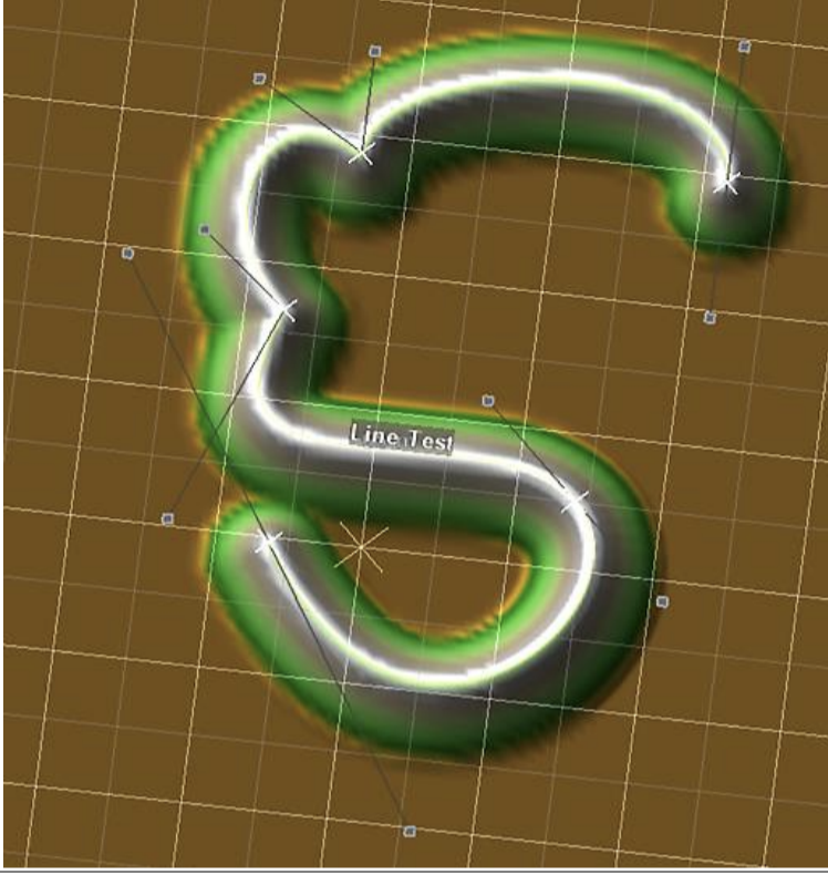
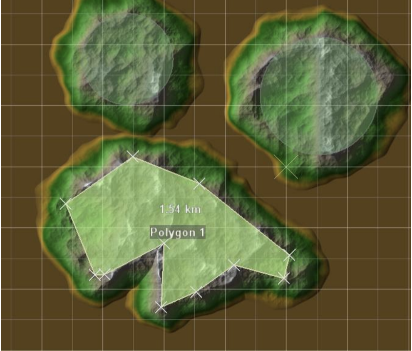
On the left is the Shape Library, where you can access the various shapes available for you to draw. To create a new shape, simply select the variety you desire from the libray, and click-drag in the terrain area. All shapes are created in a similar way, although some allow you more flexibility during shape creation. For example, polygon and path shapes can be either sketched or plotted more precisely by clicking individual vertices rather than dragging.
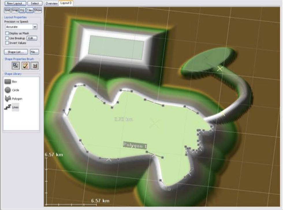
Note that around each created shape there is a “transition zone”, where the shape’s influence fades away to the background. When multiple shapes overlap, the one with the greatest height governs. You can also choose to set a shape to Subtractive mode, in which case it will be subtracted from all of the positive shapes at that same point.
Shapes can be selected by left-clicking on them. Multiple shapes can be either drag-selected using the selection marquee, or added to the selection individually by holding down shift while clicking on new shapes.
Shape Properties Once a shape has been created, you can bring up a shape’s properties by double-clicking on it: All shapes have several properties in common that can be edited.
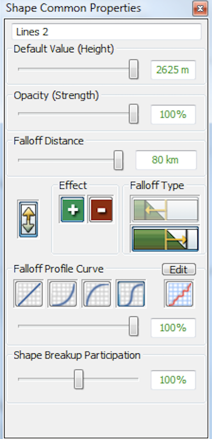
● Default Value: Controls the height value of the shape
● Opacity: The power of this shape versus the background. Low opacity values allow background heights to show through.
● Falloff distance: the distance between the border of the shape and the region in which the shape has no influence on the terrain.
● Falloff type: Many shapes allow you to how you wish the falloff zone to be defined:
○ Exterior falloff means that the shape is full strength to the border, and then falls away on the outside of the shape.
○ Interior falloff means the shape’s falloff occurs inside of the shape, reaching no influence at the border of the shape.
● Operation: Shapes may be positive or negative. A negative shape is subtracted away from other existing shapes.
● Shape Falloff function: you can select from a variety of preset falloff functions.
○ Linear falloff provides an even gradient to the falloff.
○ Squared falloff provides gentle lower regions and a sharp ridge on top.
○ Square root falloff provides a gentle top transition and steep lower areas
○ S-falloff provides smooth falloff on both the top and bottom of the shape.
○ Custom falloff allows you to define a custom falloff function, which can be very useful for among other things, defining road and river profiles.
● Falloff Fader: Llets you control how much influence the falloff function chosen above has on the falloff curve. A value of 0% will always give you a linear falloff gradient, while 100% means that you are using the chosen function.
● Shape Breakup Participation: Controls the extent to which this shape is effected by the Layout Generator’s fractal breakup setting.
Transforming Shapes
Dragging a selected shape will move the shape in the direction you drag. Right-clicking brings up the a context menu for the selected shapes:
All shapes support at least some transformation options. These allow you to translate, rotate, or scale the selected shapes. Simply select the transformation option you want (or use the Hotkey for it from the the Layout View) and drag in the viewport to perform the action. Clicking without dragging will end the transformation mode.
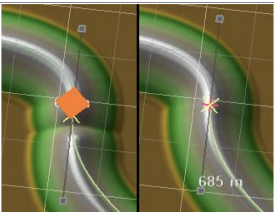
Transformation Center Holding down shift or ctrl while rotating or scaling will perform each action around the shape’s own origin rather than the center-point of the group. The graphic below illustrates the difference:
Shapes can also be copied or pasted by selecting the appropriate option from the edit menu, or using the standard CTRL-X, CTRL-C, CTRL-V shortcut keys.
Other shape options
● Enable/Disable Shape: if a shape is disabled, it no longer effects the world in any way.
● Lock Shape: make the shape unchangable until this is selected again. Use this to prevent accident modification of important shapes.
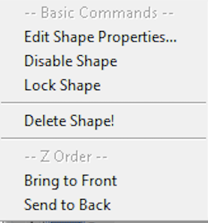
● Delete Shape: As you might expect, this deletes the currently selected shape(s)!
● Bring to Front/Send to Back: Moves the selected shapes forward or backward in the Z order. This has no effect on output, but allows you to change which shape is selected first between overlapping shapes.
Vertex-based shape options
The polygon and path tools are defined by a sequence of vertices. There are some additional editing options available for vertex based shapes.
Bezier Shapes
Vertex-based shapes support bezier splines for smoothly interpolating between each vertex. This is slower to process but is often highly desireable to create smooth and complex geometry. You can convert between linear and bezier curve segments by checking or unchecking the “Use Bezier Path” option in the right-click context menu for that shape.
If a shape has bezier curves enabled, the shape will have additional handles available representing the bezier control points for the curve.
By default, the handles on either side of a vertex are linked together to provide a smooth transition through that vertex, but you can override this behavior by holding down shift wile dragging a bezier handle. In addition, you can set all of the bezier handles in a shape at once to provide a smooth shape by selecting the “Perform Curve Smoothing” option from the context menu.
Vertex Editing
Vertices have their own context menu that you access by right-clicking on a specific vertex. This allows you to set some of their properties directly.
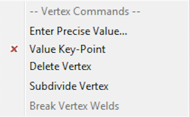
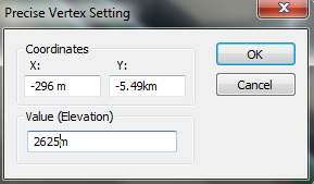
● Enter Precise Value: This option allows you to enter specific numbers for the (X,Y) coordinate of the vertex and its elevation value.
● Value Key-Point: Toggle whether the selected vertex is interpolated or whether it is a “keyframe” that has its value set manually.
● Delete Vertex: Removes the vertex from the shape, connecting the two vertices on either side together.
● Subdivide Vertex: Inserts two new vertices adjacent to the selected vertex.
● Break Vertex Welds: Break any welds that involve the selected vertex.
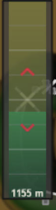
In addition, there is a quick shortcut for setting shape heights on a per-vertex basis. Right-click on a vertex and without releasing the mouse button, drag up or down to quickly set the height value of that point.
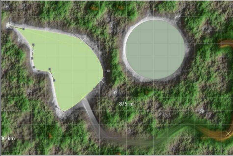
Vertex Welding
You can weld together vertices that occur on different shapes. Welded vertices will always occupy the same position in space, allowing you to link several shapes together in, for example, a road or river. To weld together vertices, simply drag one vertex over another. The cursor will highlight to show the potential welding action.
After welding, any transformations performed on one shape that effect that vertex will also move the linked vertex in the other shape(s).
If you decide later that you wish to break the weld, simply select the vertex or shape in question and right-click to bring up the context menu, and select “Break Weld”
Fractal Breakup
Fractal Breakup allows you to distort the unnaturally straight edges often produced by the geometric primitives. This is often desirable when creating natural shapes.
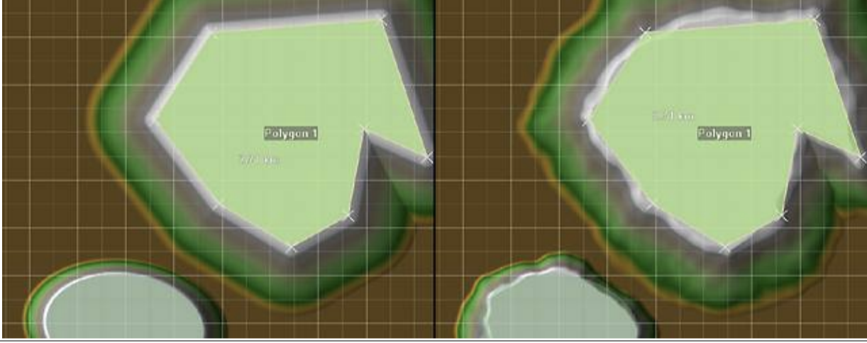
Fractal Breakup must be enabled on a per-layout basis when you want to use it. However, you can decide on a per-shape basis which shapes are distorted by changing that Shape’s “Fractal Breakup Participation” value.
You can change the scale and intensity of the breakup effect by editing the Fractal Breakup properties:
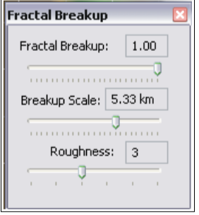
● Fractal Breakup: The intensity of the effect. Lower values provide a more subtle distortion.
● Breakup Scale: The distance that the distortion effect is applied for. Large values will produce slowly varying but large amplitude variations, while low values produce more of a ripple effect. ● Roughness: The complexity of the edge. This number corresponds to the number of octaves of fractal noise to be applied.
Sourcing vs. Modifying terrain with a Layout Generator
You can use the Layout Generator in your world in two different ways.
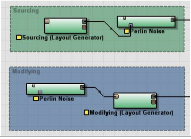
1. Use the Layout Generator as a Generator, creating terrain or mask information to be wired to a different device in the world.
2. Use the Layout Generator to modify an existing terrain by connecting that terrain into the Primary input port on the LG.
Deciding on the type of connection to use You should use the Layout Generator as a source of terrain when you want to generate guide shapes for a fractal generator or a mask for a particular effect. The image below shows the result of connecting the output of a Layout Generator to a Perlin Noise device:
On the other hand, you should use the Layout Generator to modify the terrain when you want to embed shapes into the terrain.
For example, leveling areas to a certain height, creating a road that cuts/fills through an existing terrain, or inserting waterways.
Importing and Exporting Shapes
You can import or export shapes with one of several vector-graphics art formats. In particular, the SVG and AI formats are supported.
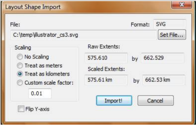
Import Scaling How to scale the raw coordinates is the most important decision when moving shapes to and from World Machine. You can have WM treat the file coordinates as meters, kilometers, a custom scale factor. A display shows you the current region to be exported to a file.
You can also choose to flip the Y-axis of all of the imported shapes; this is useful when interacting with a program that measures from an origin in the top-left corner instead of the bottom-left system that World Machine uses.
Note that there are some serious limitations in what information can be imported or exported; any per-vertex data you have set will be lost, and World-Machine specific shape information also will not transfer. Nonetheless it can be very useful to be able to re-use vector data from other sources or export the exact paths of splines to the next stage in your production pipeline.
Curve Editor
Layout View contains a curve editor to allow you to define custom falloff profiles for shapes as well as view the elevation profile of a vertex based shape.
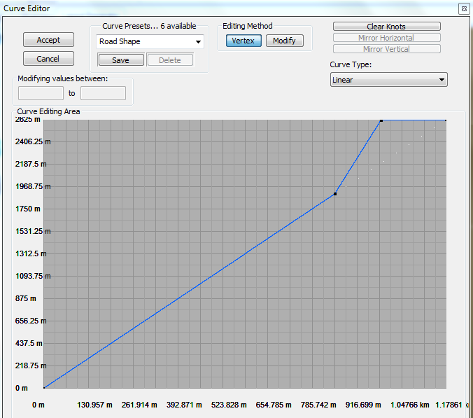
The horizontal axis shows the distance along the curve, while the vertical axis shows elevation. The curve editor works in one of several modes depending on what you’re editing; when modifying a falloff curve, you can freely add new knots to the curve. When editing a lofting curve (heights along a path), the knots are fixed in position and can only be changed in height. These two modes of operating are reflected in the Editing Method:
● Vertex mode allows you to add or delete vertices, and move them horizontally
● Modify mode allows you to change the height of existing points only
Lastly, you can load and save preset falloff curves so that you can re-use particular profiles among layouts or projects.